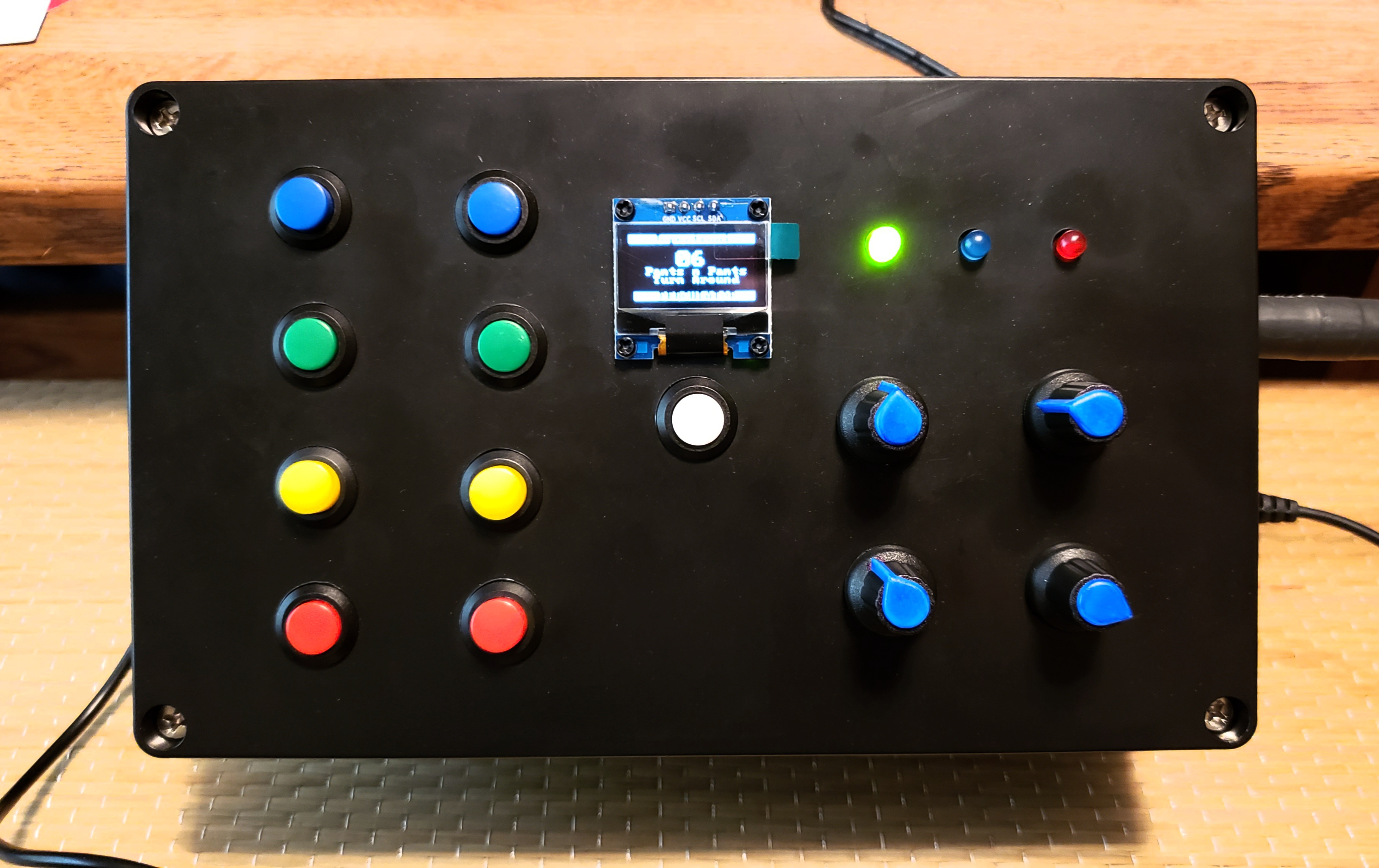
Root Commander is a smart Arduino MIDI controller that sends single note commands when a button is pressed. The scale or 'mode', key, and octave are selected with 3 potentiometers. Then the note or 'step' in that scale is sent out via MIDI when you press any of 7 normally open, momentary buttons. Every note you play will always be in tune with the scale you selected because Root Commander sets the proper notes for you on the 7 step buttons. There are only 7 instead of 8 because the 8th note of a scale is the same as the first note but 1 octave higher. You can play that note by shifting the octave pot up one octave and playing button 1. An OLED display is used to show the scale, key, octave, and step (shown in Roman Numerals) you've selected.
How to Use Root Commander
- Use a 5 pin MIDI cable to connect Root Commander to a sound generating instrument such as a synth or computer DAW.
- On Root Commander select the scale or mode you want to play in with the scale pot. Included scales are Major, Minor, Dorian, and Mixolydian.
- Then select the key you want to play in with the key pot. Starting from all the way counter clockwise, the note selection goes from A2 chromatically up to Ab3 at full clockwise.
- Then select the octave of the note you want to play with the octave pot. There is a 4 octave range from -2 octaves up to +1 ocatve.
- From here use any of the 7 buttons to select the note you want to play in that scale. Root Commander populates the values so that you can't play a wrong note outside the scale.
- Typically you'll set the scale and key and leave them alone. Then play using the buttons and the octave pot.
Board Info
This code is set up for an Arduino Pro Micro. The SDA and SCL pins used for I2C OLED are different on different Arduino boards, so you will need to adjust your pins in the code and the wiring if you use an Arduino Nano. On Nano SDA = A4, SCL = A5. Make these adjustments in your wiring and on lines 29 - 30 in the code.
Pro Micro has the benefit that it can be used as a native MIDI over USB instrument if coded with the usbMIDI.h library instead of the MIDI.h library. This requires changing the commands for note on and off in the code. If you use a Pro Micro be careful of the power supply you select. The generic Pro Micros I use require 5 - 7V input on Vin, and 9V may be too much. I have included a 6V power supply in the parts list below.
Code Info
Download my Arduino code and schematic from github here.
MIDI.h and ss_oled libraries are required. You will need to download them if you don't already have them. Be sure they're stored in your Arduino Libraries folder.
The Root Commander code uses a lot of memory due to storing the strings for the OLED display. There may be a better way to do this, but it functions perfectly as is. If you make adjustments to improve memory usage, let me know.
You can add more scales to the code. If you do so you'll need to add additional cases to the scale switch case portion of the code.
Space has been left between the cases in the potentiometer value readings for each case to account for flutter inherent to potentiometer readings. Without the gap between the end of one case and start of the next case you could have the potentiometer dialed right on the edge of one case and have it switch to the next case on its own without you touching the potentiometer due to constant and inherent noise in the signal. This is not desirable, so I included buffers in the case values.
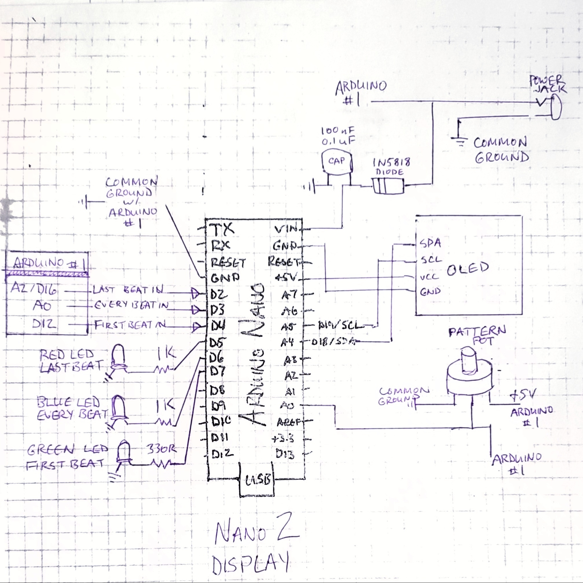
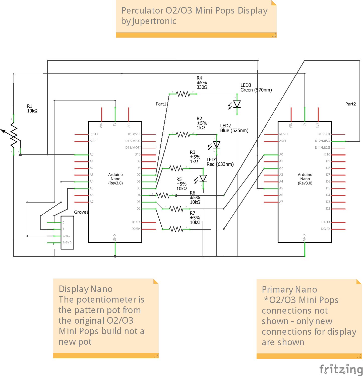
Schematic

MIDI and 5 Pin DIN Socket Info
Please see the schematic I posted and also look at the MIDI diagram I posted so that you don't flip which pins to use on the MIDI socket when you're soldering this up. This is looking at the back of the socket where the lugs come out.

I have some code commented out that you can use to send MIDI note off commands. I have this set up to play nicely with my Skeeter sequence synth, but you may want to add the note off commands. You can do this by sending a note on command with a 0 velocity. Some instruments prefer that and will not respond to note off commands. So just use note on commands with 0 velocity to be safe.
Pro Micro boards support native USB MIDI, so you can plug this build into your computer via the onboard USB and send MIDI commands from the Root Commander that way instead of the 5 pin MIDI socket. Cool, huh? If you want to use your Root Commander that way, replace the MIDI.h library with the usbMIDI.h library and change the MIDI commands to the appropriate command syntax used in the usbMIDI.h library.
I find the good 'old fashioned' 5 pin DIN MIDI socket to be the most versatile allowing you to make easy connections to standalone instruments such as synthesizers as well as to a computer. You just need the right cable. See my parts list below for MIDI to MIDI and MIDI to USB cables.
My Motivation
Disclaimer
I'm just a woman who loves making my own instruments and making music. I'm not a coding expert or schematic creation wizard. But I hope this helps!
Sharing
I invite you to use this code or build your own Root Commander with attribution reference back to this original project.