Start with the video demo by clicking above or clicking Here
Here's my Github repository with code and schematics: Jupertronic Perculator
About
Perculator is essentially an OLED display addition to the Arduino based Mini Pops drum machine originally designed by Jan Ostman.
I've also made significant changes to the drum sequences to emulate 80s electro pop and dance beats.
*This project runs on 2 Arduinos connected through a common ground, the pattern pot, and a few pins*
Board 1 runs a sound generating drum machine with sounds emulating the Korg Mini Pops. This code, Perculator, is a modified version of The Wee O3 (Mark Dammer) expansion of O2 Mini Pops (Jan Ostman) code which has been popularized by Bloghoskins.
- Minor changes made for sending pulsed outputs for Perculator's 3 LED design.
- Extensive changes made to the beat patterns to produce 80s 4 on the floor dance beats
- Switched to 8ths (1 and 2 and 3 and 4 and) instead of 16ths to work with timing input from my Skeeter sequence synth project
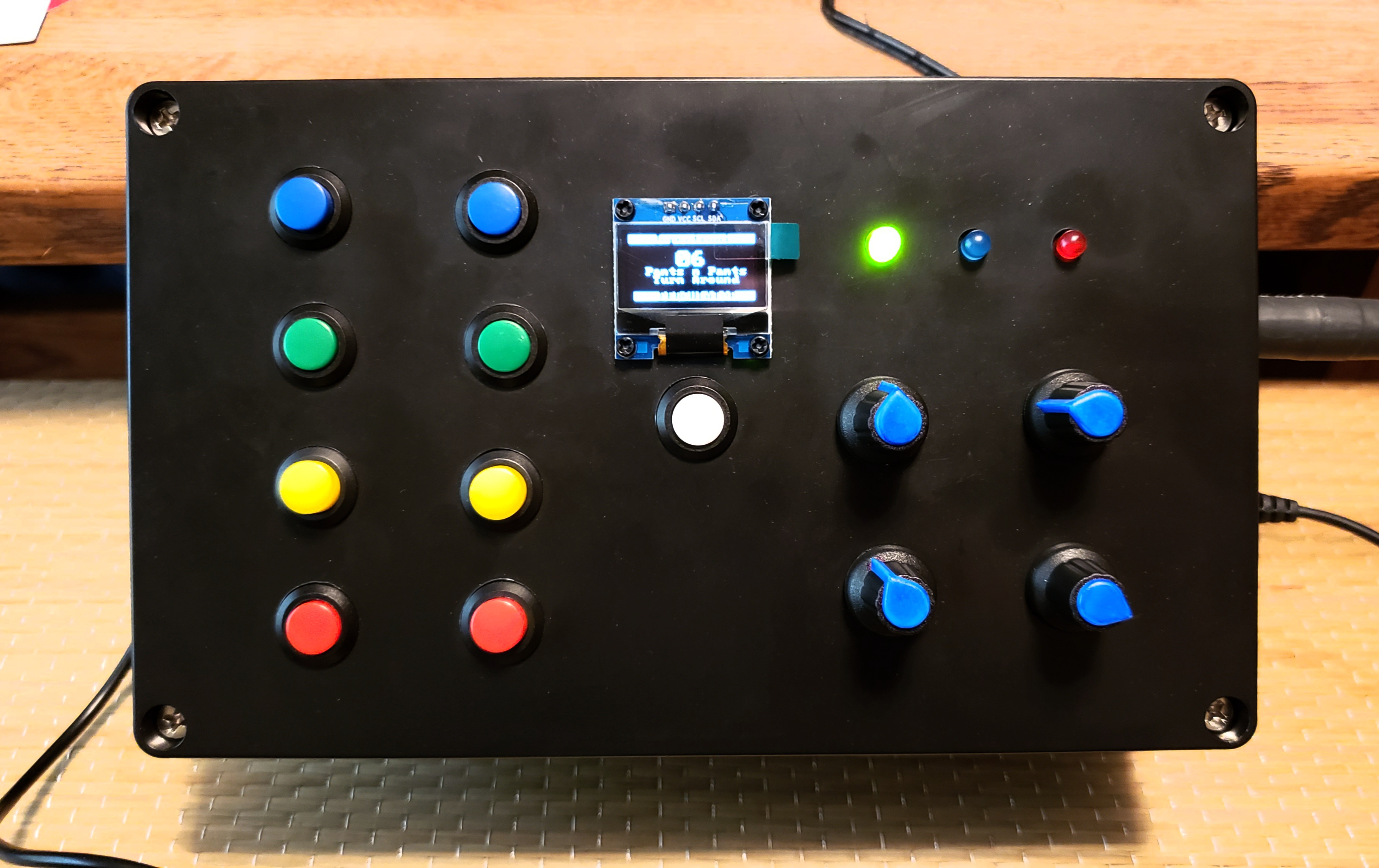
Board 2 runs original code operating an OLED screen showing the number and name of the drum pattern selected by the pattern pot and 3 LEDs which are userful for live play for visual cues showing the beats so you can syncronize your changes with the first/last beat of a sequence.
- LED 1 blinks on the first note of the beat sequence
- LED 2 blinks on each beat of the sequence
- LED 3 blinks on the last note of the beat sequence
Fabricating
Breadboard prototype


The 2 Arduino Nanos are installed on solderable breadboard (more expensive than perf board but easier for a beginner like me to use) with connections from the potentiometers, buttons, LEDs, and power inputs.

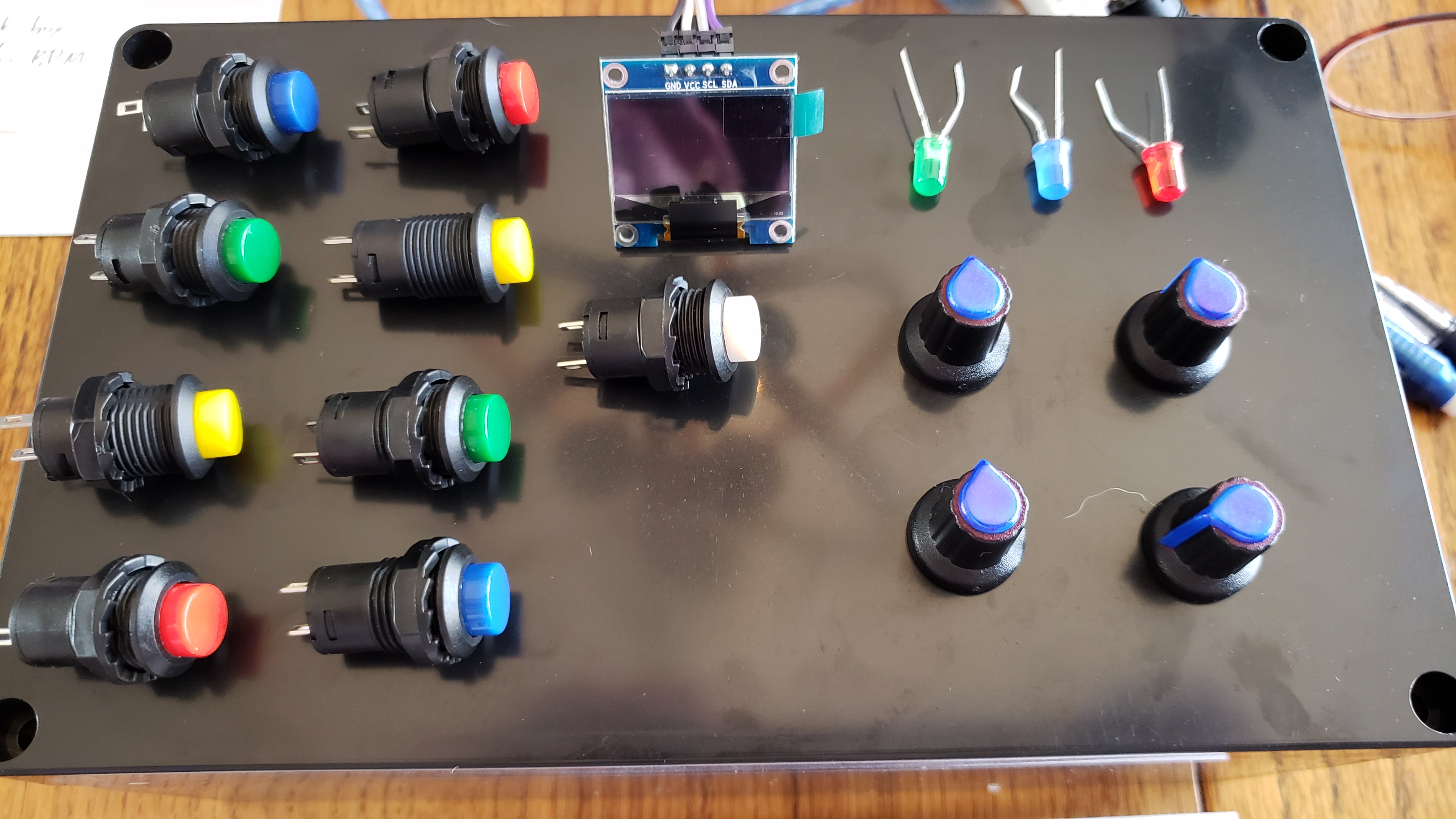
The full interior of the build: The boards are powered by a single input jack wired separately to each board. I labeled the leads from the buttons for which digital pin to solder them to on Arduino 1 because I wanted specific sounds on adjacent buttons in order to have the bass drum, snare, high hat, and cow bell together on the button interface for better playability.


Parts Links
Code Installation
I've posted my code here on Github.
Install Jupertronic_Perculator_O3Minipops.ino on board 1. *Include Perculator_data.h in the same sketch folder when you upload.
Install Jupertronic_Perculator_Display.ino on board 2. You will need to install the ss_oled.h library for the OLED.
Wiring
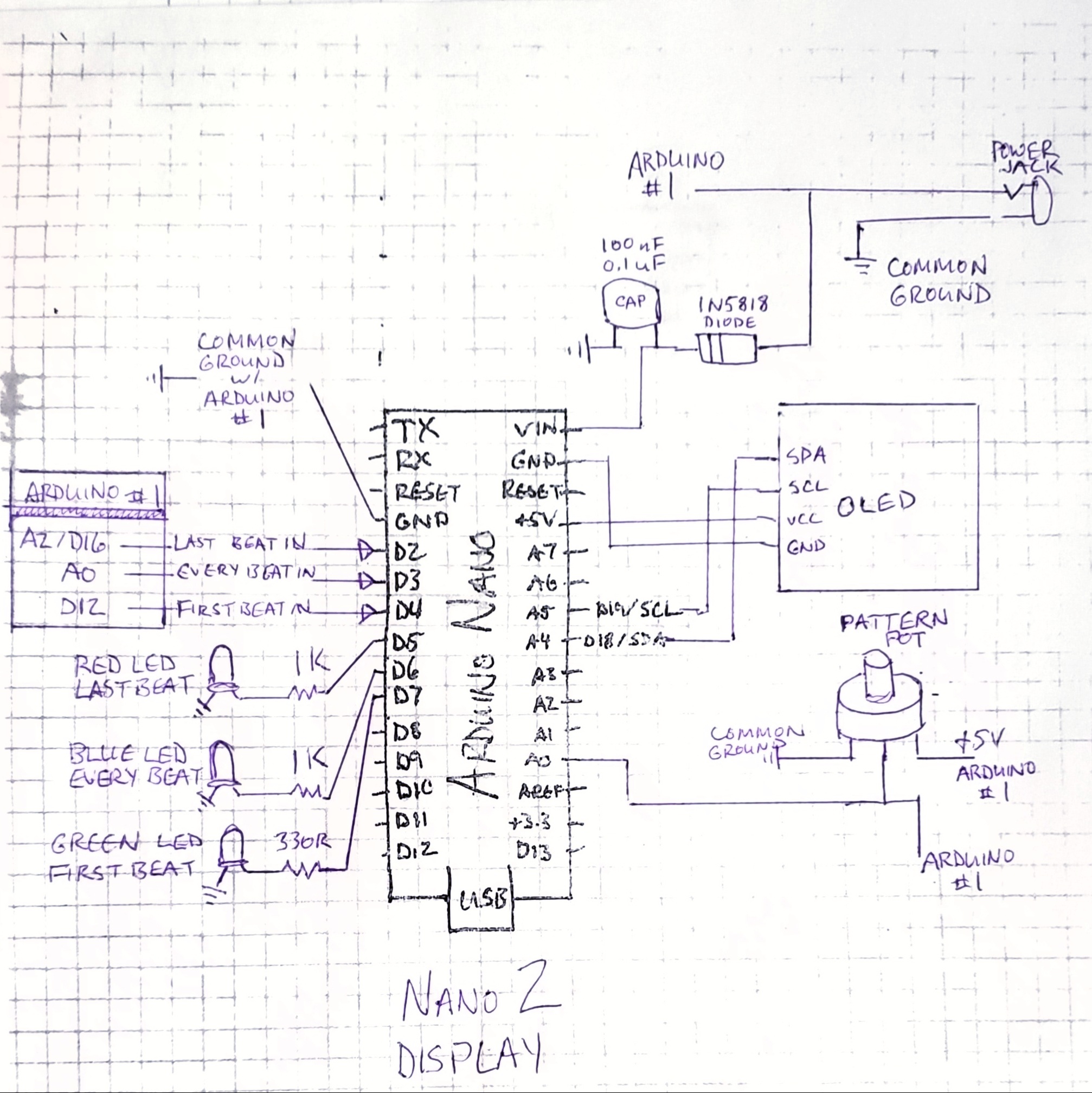
The first Arduino which handles all the noise making should be wired according to The Wee O3 schematics. The schematics detailed by Mark Dammer for The Wee O3 are here https://github.com/mark-orion/The-Wee-O3 . Add the changes shown above in Perculator_Display_schem.pdf and Perculator_Display_diagram.jpg available for download in my github repository.
Also see Bloghoskins' detailed drawings for the original O2 Mini Pops. This version has simplified controls with 2 potentiometers and fewer sync options. http://bloghoskins.blogspot.com/2016/11/korg-mini-pops-diy-drum-machine.html
With your sound generating board all wired up, move on to the OLED board using my plans.
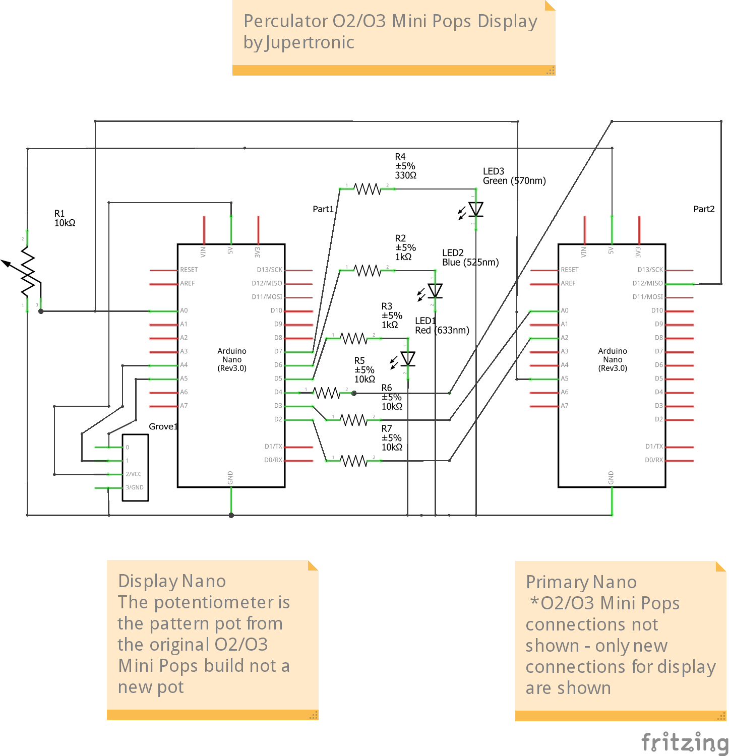
Wire board 2 according to the Fritzing schematic and drawing posted at the top of this section above.
- Connect grounds from board 1 and board 2 to a common ground point.
- Run 2 wires from the middle signal lug of the pattern pot so that it can be connected as an input to both Arduino boards.
- Be sure the ground lug of pattern pot is connected to the common ground.
- Power the pattern pot only from board 1.
- Connect the other pins as shown in the schematic for inputs to board 2 from board 1 for timing pulses and the LEDs.
- LEDs can be run off board 1 as in The Wee O3. They are split off to the extra capacity of board 2 here to remove possible audio coloration on board 1.
- Suggest green LED for first beat, blue LED for each beat, and red LED for last beat.
- Suggest a smaller resistor on the green LED because the red and blue are brighter. This evens it out with my parts. Value determined by trial and error.
- My LEDs are very bright in the dark but good in a light room. Use larger resistors to dim the LEDs.
- You could put diodes on the connections between board 1 and 2 if desired.
Pattern Names
Change the pattern names as desired in the display code. These Perculator beats are promarily 4 on the floor 80s dance beat sequences. 'Boots n' pants' is slang for beat box sounds. ;)
General
OLED display and LED interface code by Jupertronic aka Janis Wilson Hughes aka J Dub aka vitalWho aka Evolution Stoneware (youtube).
OLED shows what pattern you're playing with pattern number and pattern name so you can tell what the heck you've selected on the pattern potentiometer.
Pins for OLED are dependent on type of Arduino used. This is set up for Nano. If you're using Pro Micro SDA = D2, SCL = D3. Check your SDA & SCL and adjust accordingly.
Disclamer
I'm neither a coding expert nor a Fritzing wiz, but I hope this helps!
Links
Perculator github code and schematics for download
My tip jar - donations appreciated
Bloghoskins O2 Mini Pops post and discussion - tons of great info
Video of The Wee O3 upgraded O2 Mini Pops by Mark Dammer
Github repository for The Wee O3 with code and schematics
Thank you!
Big thanks to Bloghoskins, Jan Ostman, and Mark Dammer.
Wishing wellness and wellbeing to all.
- Janis


No comments:
Post a Comment